
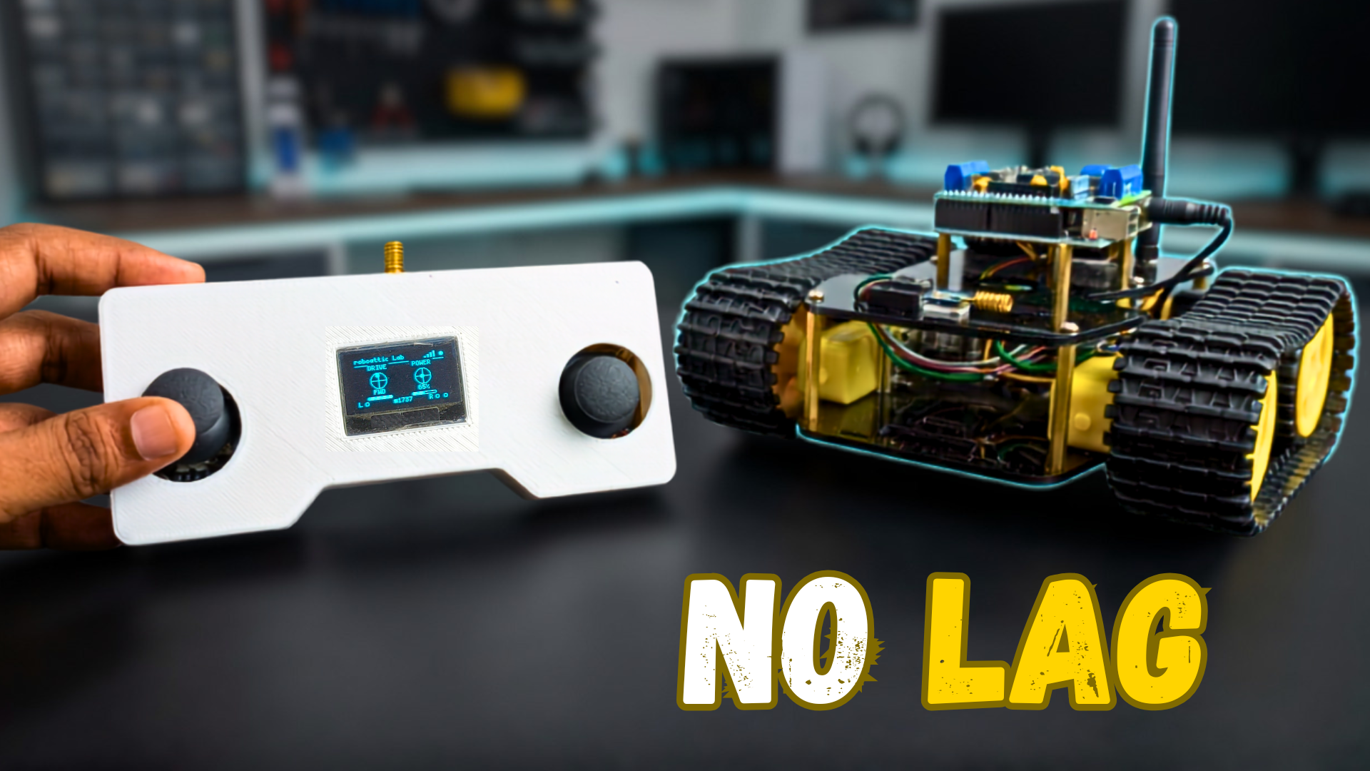
DIY Long-Range LoRa RC Tank Using Arduino Uno | Complete Build Guide
Quick Navigation
In my previous project, I built a custom long-range LoRa controller from scratch using the Reyax RYLR998 module. While the controller worked well, many viewers noticed one important issue during testing. The receiver occasionally responded with noticeable latency, making the RC tank feel less responsive than expected.
Rather than leaving it as it was, I decided to investigate the problem, redesign the receiver, and optimize both the hardware and firmware to improve the overall driving experience.
In this guide, I'll show you how I built a dedicated LoRa receiver and integrated it into a tracked Arduino RC tank. Along the way, you'll learn how to assemble the chassis, mount the electronics, wire the LoRa module safely using a voltage divider, upload the firmware, and test the completed system.
If you haven't built the transmitter yet, I highly recommend starting with my previous guide first, since this receiver is designed to work with that controller.
Previous Project:
Custom Long-Range LoRa Controller From Scratch: https://www.roboatticlab.com/blogs/how-i-built-a-custom-long-range-lora-controller-from-scratch
By the end of this tutorial, you'll have a fully functional long-range LoRa-controlled RC tank that is smoother, more responsive, and ready to be used as a platform for your own robotics projects.
Supplies

To build this LoRa RC tank, you'll need the following components:
Mechanical Components
- Acrylic tank chassis panels (body frame)
- Screws, standoffs, spacers, and mounting hardware
- 2× BO DC geared motors
- 4× Tank track hub adapters
- 2× Continuous rubber tank track loops
Find them at: https://jlcmc.com/?from=RL2
Electronics
- Arduino Uno
- L298D Motor Driver Shield
- Reyax RYLR998 LoRa Module
- 1× 2-cell (2×18650) battery holder
- 2× 18650 Li-ion batteries
- Small perfboard (for the voltage divider circuit)
- Assorted jumper wires
- 20 KΩ & 10 KΩ Register
Tools
- Phillips screwdriver
- Soldering iron and solder
- Wire stripper/cutter
- Hot glue gun (optional)
Step 1: Assemble the Tank Chassis


In this step, we'll assemble the complete mechanical structure of the RC tank.
- Mount the two BO geared motors onto the lower acrylic chassis using the provided screws and motor brackets.
- Ensure all motors are facing the correct direction and are firmly secured.
- Install the metal spacers (standoffs) onto the lower acrylic panel using the appropriate screws.
- Attach the drive pulleys (motor hubs) to the shafts of all two motors and tighten them securely.
- Install the idler gears (free-rotating wheels) on the opposite side of the chassis.
- Verify that all pulleys and idler gears rotate freely without touching the acrylic frame.
- Carefully stretch the tank tracks over the drive pulleys and idler gears on both sides of the chassis.
- Rotate the tracks by hand to ensure smooth movement and proper alignment.
Your tank chassis is now assembled and ready for installing the electronics in the next step.
Step 2: Elevate Your Electronic Projects - JLCMC


JLCMC is your one-stop shop for all electronic manufacturing needs, offering an extensive catalog of nearly 600,000 SKUs that cover hardware, mechanical, electronic, and automation components. Their commitment to guaranteeing genuine products, rapid shipping (with most in-stock items dispatched within 24 hours), and competitive pricing truly sets them apart. In addition, their exceptional customer service ensures you always get exactly what you need to bring your projects to life.
For my next project, I'm planning to buy a timing belt from their Transmission Components section. What I really like is how easy it is to customize the part. On the left side, you can select all the required options, and just below that, you get the complete specification and documentation, so you know exactly what you're ordering.
If you're building this project, you can also find many of the required components such as screws, nuts, standoffs, bearings, shafts, timing belts, pulleys, and other mechanical hardware on JLCMC. Explore their complete catalog here: https://jlcmc.com/?from=RL2
JLCMC has recently upgraded their new-user registration benefits, increasing the value of the welcome coupon package to $123 in discount coupons. Whether you're building DIY electronics, robotics, or mechanical projects, JLCMC has you covered with quality parts and fast delivery. Don't miss out. Visit https://jlcmc.com/?from=RL2 to explore their extensive product range and claim your new-user discount coupons today.
Step 3: Install the Upper Chassis


In this step, we'll mount the Arduino Uno, motor driver shield, and complete the upper chassis assembly.
- Attach the mounting spacers to the upper acrylic panel at the Arduino mounting holes.
- Place the Arduino Uno onto the spacers and secure it using the appropriate screws.
- Carefully align the L298D Motor Driver Shield with the Arduino Uno headers.
- Gently press the motor driver shield onto the Arduino Uno until all the header pins are fully seated.
- Double-check that the shield is properly aligned and firmly connected to the Arduino.
- Position the assembled upper chassis above the lower chassis.
- Align the upper acrylic panel with the standoffs installed in the previous step.
- Secure the upper chassis to the standoffs using the provided screws.
- Make sure all screws are tightened evenly without overtightening the acrylic panels.
The upper chassis is now assembled and ready for the wiring and circuit connections in the next step.
Step 4: Circuit Connection


Now it's time to connect all the electronics inside the tank.
- Connect the two BO geared motors to the output terminals of the L298D Motor Driver Shield.
- Route the motor wires neatly to avoid interference with the rotating tracks.
- Assemble the voltage divider circuit on a small perfboard using the required resistors.
- Solder all the connections securely and verify the output voltage before connecting the LoRa module.
- Connect the Reyax RYLR998 LoRa module to the Arduino Uno according to the circuit diagram.
- Connect the RX pin of the LoRa module through the voltage divider circuit to safely interface with the Arduino's 5 V logic.
- Secure the LoRa module and the voltage divider PCB to the chassis using screws, double-sided tape, or hot glue to prevent movement while driving.
- Install the 2×18650 battery holder in its designated mounting position on the chassis.
- Connect the battery holder to the power input of the motor driver shield, ensuring the polarity is correct.
- Double-check all wiring connections before powering on the system. Verify that there are no loose wires or short circuits.
The receiver hardware is now fully assembled and ready for uploading the firmware in the next step.
Step 5: Upload the Firmware


What's New in This Firmware?
The original version of the project used SoftwareSerial to communicate with the Reyax LoRa module. During testing, I observed noticeable latency and occasional delays in the receiver's response.
To improve the responsiveness, I updated both the hardware configuration and the firmware. The communication between the Arduino and the LoRa module was optimized, and several changes were made to reduce unnecessary processing delays and improve packet handling.
As a result, the RC tank responds much faster to joystick inputs, making the driving experience significantly smoother and more responsive compared to the previous version.
If you're upgrading from my original LoRa controller project, I highly recommend uploading both the updated transmitter firmware and the new receiver firmware to achieve the best performance.
In this step, you'll upload the receiver firmware to the Arduino Uno and update the transmitter firmware with the latest optimized version.
Receiver Code
Paste the following receiver code into a new Arduino IDE sketch.
/*
 * ============================================================
 *  Code by: Shahbaz Hashmi Ansari
 *  LoRa RC RECEIVER — Tank
 * ============================================================
 *  UNO A0 = RX (connect to RYLR998 TX)
 *  UNO A1 = TX (connect to RYLR998 RX)
 * ============================================================
 */

#include <SoftwareSerial.h>
#include <AFMotor.h>

SoftwareSerial loraSerial(A0, A1); // RX, TX

AF_DCMotor motorL(1); // M1 — Left track
AF_DCMotor motorR(4); // M4 — Right track

#define DEAD_ZONE   15
#define MIN_PWM     60
#define TIMEOUT_MS  500

// ── State ──
String  rxBuf = "";
int     lx, ly, currentSpeedPct, ry, lBtn, rBtn;
bool    eStop = false;
unsigned long lastPacket = 0;

String sendAT(const char* cmd, int waitMs = 300) {
  loraSerial.println(cmd);
  delay(waitMs);
  String resp = "";
  while (loraSerial.available()) resp += (char)loraSerial.read();
  return resp;
}

void stopAll() {
  motorL.run(RELEASE);
  motorR.run(RELEASE);
  motorL.setSpeed(0);
  motorR.setSpeed(0);
}

void driveMotors(int throttleVal, int turnVal, int speedPct) {
  int throttle = throttleVal - 127;
  int turn     = turnVal - 127;

  if (abs(throttle) < DEAD_ZONE && abs(turn) < DEAD_ZONE) {
    stopAll();
    return;
  }

  int leftSpeed, rightSpeed;

  if (abs(throttle) < DEAD_ZONE && abs(turn) >= DEAD_ZONE) {
    leftSpeed  = turn;
    rightSpeed = -turn;
  } else {
    leftSpeed  = throttle + turn;
    rightSpeed = throttle - turn;
  }

  leftSpeed  = constrain(leftSpeed,  -127, 127);
  rightSpeed = constrain(rightSpeed, -127, 127);

  // Apply speed multiplier based on the saved state from the transmitter!
  leftSpeed  = (int)((long)leftSpeed  * speedPct / 100);
  rightSpeed = (int)((long)rightSpeed * speedPct / 100);

  if (abs(leftSpeed) > DEAD_ZONE) {
    motorL.run(leftSpeed > 0 ? FORWARD : BACKWARD);
    motorL.setSpeed(map(abs(leftSpeed), 0, 127, MIN_PWM, 255));
  } else {
    motorL.run(RELEASE);
    motorL.setSpeed(0);
  }

  if (abs(rightSpeed) > DEAD_ZONE) {
    motorR.run(rightSpeed > 0 ? FORWARD : BACKWARD);
    motorR.setSpeed(map(abs(rightSpeed), 0, 127, MIN_PWM, 255));
  } else {
    motorR.run(RELEASE);
    motorR.setSpeed(0);
  }
}

void parsePacket(String raw) {
  if (!raw.startsWith("+RCV=")) return;

  for (int i = 0; i < raw.length(); i++) {
    char c = raw[i];
    if (c != '+' && c != '=' && c != ',' && c != '-' &&
        !isDigit(c) && !isAlpha(c)) return;
  }

  String data = raw.substring(5);
  int vals[10];
  int idx = 0, start = 0;

  for (int i = 0; i <= (int)data.length() && idx < 10; i++) {
    if (i == (int)data.length() || data[i] == ',') {
      vals[idx++] = data.substring(start, i).toInt();
      start = i + 1;
    }
  }

  if (idx < 8) return;

  lx   = vals[2];
  ly   = vals[3];
  // Index 4 is now directly receiving the persistent speed 30-100% from TX
  currentSpeedPct = constrain(vals[4], 30, 100);
  ry   = vals[5];
  lBtn = vals[6];
  rBtn = vals[7];

  lastPacket = millis();
  eStop = (lBtn == 1);

  Serial.print(F("T:")); Serial.print(lx);
  Serial.print(F(" S:")); Serial.print(ly);
  Serial.print(F(" SPD:")); Serial.print(currentSpeedPct);
  Serial.print(F("% E:")); Serial.println(eStop ? "Y" : "n");

  if (eStop) {
    stopAll();
    return;
  }

  driveMotors(lx, ly, currentSpeedPct);
}

void setup() {
  Serial.begin(9600);
  delay(1000);

  loraSerial.begin(9600);
  rxBuf.reserve(64);

  motorL.setSpeed(0); motorL.run(RELEASE);
  motorR.setSpeed(0); motorR.run(RELEASE);

  Serial.println(F("================================="));
  Serial.println(F(" LoRa RC RX — Tank Chassis"));
  Serial.println(F("================================="));
  delay(500);

  String r = sendAT("AT", 500);
  Serial.println(r.indexOf("+OK") != -1 ? F("RYLR998: OK!") : F("RYLR998: FAIL!"));

  loraSerial.println("AT+ADDRESS=2");  delay(300);
  while (loraSerial.available()) loraSerial.read();

  loraSerial.println("AT+NETWORKID=6"); delay(300);
  while (loraSerial.available()) loraSerial.read();

  loraSerial.println("AT+BAND=915000000"); delay(300);
  while (loraSerial.available()) loraSerial.read();

  loraSerial.println("AT+PARAMETER=7,9,1,12"); delay(300);
  while (loraSerial.available()) loraSerial.read();
  Serial.println(F("Ready."));
}

void loop() {
  while (loraSerial.available()) {
    char c = loraSerial.read();
    rxBuf += c;
    if (c == '\n') {
      rxBuf.trim();
      parsePacket(rxBuf);
      rxBuf = "";
    }
  }

  if (millis() - lastPacket > TIMEOUT_MS && lastPacket > 0) {
    stopAll();
  }
}
Updated Transmitter Code
Replace the existing transmitter sketch with the updated version below.
/*
 * ============================================================
 *  Code by: Shahbaz Hashmi Ansari
 *  LoRa RC TRANSMITTER — Arduino Nano
 * ============================================================
 */

#include <SoftwareSerial.h>
#include <U8g2lib.h>
#include <Wire.h>

SoftwareSerial loraSerial(2, 3);
U8G2_SH1106_128X64_NONAME_1_HW_I2C u8g2(U8G2_R0, U8X8_PIN_NONE);

#define JOY_L_X    A0
#define JOY_L_Y    A1
#define JOY_R_X    A2
#define JOY_R_Y    A3
#define JOY_L_BTN   4
#define JOY_R_BTN   5
#define DEAD_ZONE  60

#define TX_INTERVAL_MS    120
#define OLED_INTERVAL_MS  200

unsigned long lastSend    = 0;
unsigned long lastDisplay = 0;
unsigned long txCount     = 0;
bool          loraOK      = false;
char          payload[32];
char          loraCmd[64];
char          buf[22];

// ── Persistent Speed State ──
int currentSpeed = 65;

// ── Cached HUD values ──
const char* hudDir = "IDLE";
int     hudThrottle = 0;
int     hudSpeedPct = 65;
bool    hudLBtn = false;
bool    hudRBtn = false;
int     hudLX = 512, hudLY = 512;
int     hudRX = 512, hudRY = 512;

void sendAT(const char* cmd, int waitMs = 300) {
  loraSerial.println(cmd);
  delay(waitMs);
  while (loraSerial.available()) loraSerial.read();
}

bool sendATCheck(const char* cmd, int waitMs = 500) {
  loraSerial.println(cmd);
  delay(waitMs);
  char resp[20] = "";
  int i = 0;
  while (loraSerial.available() && i < 19)
    resp[i++] = loraSerial.read();
  return strstr(resp, "+OK") != NULL;
}

const char* getDir(int x, int y) {
  bool fwd  = y < (512 - DEAD_ZONE);
  bool bwd  = y > (512 + DEAD_ZONE);
  bool lft  = x < (512 - DEAD_ZONE);
  bool rgt  = x > (512 + DEAD_ZONE);
  if (fwd && lft)  return "FWD-L";
  if (fwd && rgt)  return "FWD-R";
  if (bwd && lft)  return "BWD-L";
  if (bwd && rgt)  return "BWD-R";
  if (fwd)         return "FWD";
  if (bwd)         return "BWD";
  if (lft)         return "LEFT";
  if (rgt)         return "RIGHT";
  return "IDLE";
}

void showSplash() {
  u8g2.firstPage();
  do {
    // Squeezed away from borders
    u8g2.setDrawColor(1);
    u8g2.drawRBox(18, 6, 92, 18, 3);
    u8g2.setDrawColor(0);
    u8g2.setFont(u8g2_font_profont11_tf);
    u8g2.drawStr(28, 18, "roboattic Lab");

    u8g2.setDrawColor(1);
    u8g2.setFont(u8g2_font_5x7_tr);
    u8g2.drawStr(46, 36, "x REYAX");

    u8g2.drawStr(20, 50, "LoRa RC Controller");
    u8g2.drawHLine(20, 54, 88);
  } while (u8g2.nextPage());
  delay(2500);
}

void updateHUD() {
  u8g2.firstPage();
  do {
    // 1. HEADER (Shifted safely away from X=0 and X=127)
    u8g2.setFont(u8g2_font_5x7_tr);
    u8g2.drawStr(4, 8, "roboattic Lab");

    // Antenna Bars (Ends at X=111, safely inside the screen)
    u8g2.drawBox(95, 7, 2, 2);
    u8g2.drawBox(99, 5, 2, 4);
    u8g2.drawBox(103, 3, 2, 6);
    u8g2.drawBox(107, 1, 2, 8);
    // Green Link Dot (Max X = 119)
    if(loraOK) u8g2.drawDisc(117, 5, 2);
    else u8g2.drawCircle(117, 5, 2);

    // 2. DIVIDER LINES & TITLES
    u8g2.drawHLine(4, 11, 16);
    u8g2.drawStr(32 - u8g2.getStrWidth("DRIVE")/2, 18, "DRIVE");
    u8g2.drawHLine(48, 11, 26);
    u8g2.drawStr(90 - u8g2.getStrWidth("POWER")/2, 18, "POWER");
    u8g2.drawHLine(106, 11, 14);

    // 3. GIMBALS (Centered at 32 and 90)
    // Left Gimbal
    u8g2.drawCircle(32, 32, 10);
    u8g2.drawVLine(32, 22, 21);
    u8g2.drawHLine(22, 32, 21);
    int dotLX = 32 + map(hudLX, 0, 1023, -7, 7);
    int dotLY = 32 + map(hudLY, 0, 1023, -7, 7);
    u8g2.drawDisc(dotLX, dotLY, 2);

    // Right Gimbal
    u8g2.drawCircle(90, 32, 10);
    u8g2.drawVLine(90, 22, 21);
    u8g2.drawHLine(80, 32, 21);
    int dotRX = 90 + map(hudRX, 0, 1023, -7, 7);
    int dotRY = 32 + map(hudRY, 0, 1023, -7, 7);
    u8g2.drawDisc(dotRX, dotRY, 2);

    // 4. DATA TEXT LABELS (Y=50)
    u8g2.drawStr(32 - u8g2.getStrWidth(hudDir)/2, 50, hudDir);
    char spdStr[8];
    snprintf(spdStr, sizeof(spdStr), "%d%%", hudSpeedPct);
    u8g2.drawStr(90 - u8g2.getStrWidth(spdStr)/2, 50, spdStr);

    // 5. COMPACT THROTTLE/SPEED BARS
    // Left Throttle Bar
    u8g2.drawRFrame(16, 53, 32, 4, 1);
    int tw = map(hudThrottle, 0, 100, 0, 32);
    // Fixes the U8g2 rendering crash when width is too small for rounded corners!
    if(tw >= 3) {
      u8g2.drawRBox(16, 53, tw, 4, 1);
    } else if (tw > 0) {
      u8g2.drawBox(16, 53, tw, 4); // Draw square if too tiny to round
    }

    // Right Speed Bar
    u8g2.drawRFrame(74, 53, 32, 4, 1);
    int sw = map(hudSpeedPct, 30, 100, 0, 32);
    if(sw >= 3) {
      u8g2.drawRBox(74, 53, sw, 4, 1);
    } else if (sw > 0) {
      u8g2.drawBox(74, 53, sw, 4);
    }

    // 6. FOOTER ROW (Shifted securely inward)
    u8g2.drawStr(4, 64, "L");
    if(hudLBtn) u8g2.drawDisc(14, 61, 2);
    else u8g2.drawCircle(14, 61, 2);

    snprintf(buf, sizeof(buf), "#%04lu", txCount % 10000);
    u8g2.drawStr(61 - u8g2.getStrWidth(buf)/2, 64, buf);

    u8g2.drawStr(96, 64, "R");
    if(hudRBtn) u8g2.drawDisc(106, 61, 2);
    else u8g2.drawCircle(106, 61, 2);

    if (millis() - lastSend < 60) u8g2.drawDisc(117, 61, 2);
    else u8g2.drawCircle(117, 61, 2);

  } while (u8g2.nextPage());
}

void setup() {
  Serial.begin(9600);
  loraSerial.begin(9600);

  pinMode(JOY_L_BTN, INPUT_PULLUP);
  pinMode(JOY_R_BTN, INPUT_PULLUP);

  u8g2.begin();
  showSplash();

  Serial.println(F("================================="));
  Serial.println(F(" LoRa RC TX - roboattic Lab"));
  Serial.println(F("================================="));
  delay(500);

  loraOK = sendATCheck("AT");

  sendAT("AT+ADDRESS=1");
  sendAT("AT+NETWORKID=6");
  sendAT("AT+BAND=915000000");
  sendAT("AT+CRFOP=22");
  sendAT("AT+PARAMETER=7,9,1,12");
}

void loop() {
  int rawLX = analogRead(JOY_L_X);
  int rawLY = analogRead(JOY_L_Y);
  int rawRX = analogRead(JOY_R_X);
  int rawRY = analogRead(JOY_R_Y);

  bool lBtn = (digitalRead(JOY_L_BTN) == LOW);
  bool rBtn = (digitalRead(JOY_R_BTN) == LOW);

  unsigned long now = millis();

  // ── Incremental Speed Logic (Right Joystick) ──
  static unsigned long lastSpeedChange = 0;
  if (now - lastSpeedChange > 30) {
    if (rawRY < (512 - DEAD_ZONE)) {
      currentSpeed++; // Push UP = increase
      if (currentSpeed > 100) currentSpeed = 100;
      lastSpeedChange = now;
    }
    else if (rawRY > (512 + DEAD_ZONE)) {
      currentSpeed--; // Push DOWN = decrease
      if (currentSpeed < 30) currentSpeed = 30; // Min 30%
      lastSpeedChange = now;
    }
  }

  // ── CAR OUTPUT CALCULATION ──
  // Generates physical drive commands to offset the 90-degree hardware rotation
  int corrLX = 1023 - rawLY;
  int corrLY = 1023 - rawLX;
  int lxOut = map(corrLX, 0, 1023, 0, 255);
  int lyOut = map(1023 - corrLY, 0, 1023, 0, 255);

  // Left Dot:
  hudLX = rawLY;
  hudLY = 1023 - rawLX;

  // Right Dot: Directly mapped to physical stick thumb placement
  hudRX = rawRY;
  hudRY = 1023 - rawRX;

  // Cache UI Data
  hudDir      = getDir(hudLX, hudLY);
  hudThrottle = map(max(abs(hudLX - 512), abs(hudLY - 512)), 0, 512, 0, 100);
  hudSpeedPct = currentSpeed;
  hudLBtn     = lBtn;
  hudRBtn     = rBtn;

  // Send LoRa Data
  if (now - lastSend >= TX_INTERVAL_MS) {
    lastSend = now;
    txCount++;

    while (loraSerial.available()) loraSerial.read();

    snprintf(payload, sizeof(payload), "%d,%d,%d,%d,%d,%d",
             lxOut, lyOut, currentSpeed, rawRX,
             lBtn ? 1 : 0, rBtn ? 1 : 0);

    snprintf(loraCmd, sizeof(loraCmd), "AT+SEND=2,%d,%s",
             strlen(payload), payload);

    loraSerial.println(loraCmd);
  }

  // Update OLED Display
  if (now - lastDisplay >= OLED_INTERVAL_MS) {
    unsigned long gap = now - lastSend;
    if (gap > 40 && gap < (TX_INTERVAL_MS - 20)) {
      lastDisplay = now;
      updateHUD();
    }
  }
}
Upload Instructions
- Download and install the latest version of the Arduino IDE if you haven't already.
- Connect the Arduino Uno (Receiver) to your computer using a USB cable.
- Open the receiver code in the Arduino IDE.
- Go to Tools → Board and select Arduino Uno.
- Go to Tools → Port and select the COM port corresponding to your Arduino Uno.
- Click the Verify button to compile the sketch and ensure there are no errors.
- Click the Upload button and wait for the upload to complete.
- Disconnect the Arduino Uno from your computer once the upload is finished.
- Now connect the Arduino Nano (Transmitter) to your computer.
- Open the updated transmitter firmware in the Arduino IDE.
- Go to Tools → Board and select Arduino Nano.
- Select the correct COM port for the Arduino Nano.
- Click Verify to compile the sketch.
- Click Upload and wait until the upload completes successfully.
- Disconnect the transmitter from your computer and power both the transmitter and receiver.
- Verify that both LoRa modules establish communication and that the RC tank responds correctly to the joystick inputs.
The firmware installation is now complete, and your DIY LoRa RC tank is ready for testing.
Working Video & Tutorial
Congratulations! Your DIY LoRa RC Tank is now complete and ready for action.
To see the complete build process, firmware setup, and real-world testing, watch the full video tutorial below. The video covers every step of the project, including the mechanical assembly, electronics installation, circuit wiring, firmware upload, and the improvements made to reduce the latency issue.
Video Tutorial:
If you found this project helpful, consider subscribing to my YouTube channel for more DIY robotics, Arduino, ESP32, AI, and embedded systems projects.
If you build your own version of this LoRa RC Tank, I'd love to see it. Feel free to share photos of your build or ask any questions in the comments below. Happy building!
Related Articles
 arduino project
How to Make Gesture Control Robot || #MadeWithArduino
The transmitter of the car contains gyroscopic sensors which track our hand's gestures and transmit the signal to the receiver of the car and then the car works accordingly to it.
Read the full arduino project tutorial: Follow Tutorial arduino project
Build Your Own Object Tracking 4 DOF Robotics Arm With Arduino
In this project, the robotic arm will execute actions corresponding to the commands received from the sensors.
Read the full arduino project tutorial: See Project Details arduino project
DIY Arduino FFT Audio Spectrum Visualizer
Build a real-time audio spectrum visualizer using an Arduino and MAX7219 display. This DIY guide uses FFT to turn your music into a stunning light show.
Read the full arduino project tutorial: See Project Details