
How to Make Arduino Human Following Robot.
Quick Navigation
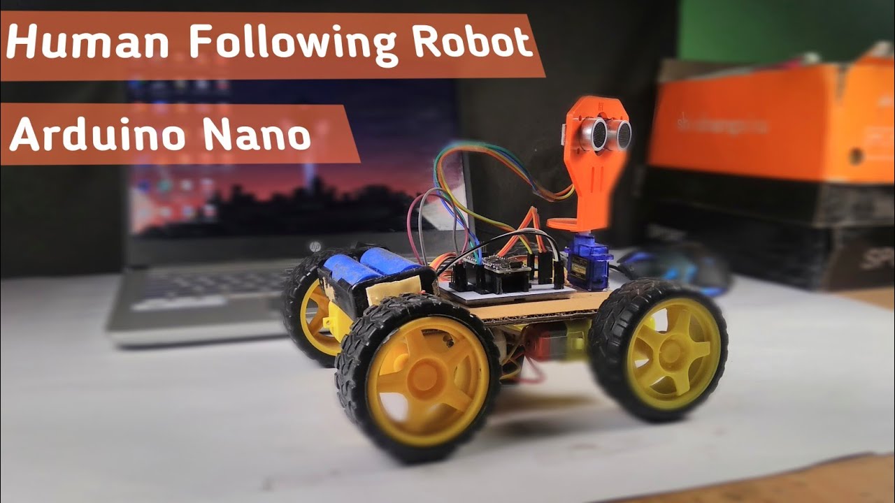
Hey guys, welcome to my article. So guys, today we are going to make a "human-following robot using Arduino Nano." Seems to be interesting, right?
Let me first tell you about the main working principle of this robot:
This human following will be having an ultrasonic sensor, which will work as a medium of tracking the object that comes in front of it. We will be coding the Arduino Nano in such a way that when an object comes near the ultrasonic sensor and if its distance is less than 5 cm, then it will go backward, and if it is more than 10 cm and less than 20 cm, then it will go forward, and if it is more than 20 cm and less than 25 cm, then it will go left, etc.
If you have not understood its working principle, then take a look at the whole tutorial; you might then understand it...
Special thanks to JLCPCB for providing me with their quality PCBs.
Key features:
- Items/gear used in the project are easily available.
- Low-cost project.
- Not much of a complicated circuit.
- Best example for learning AI.
So let's get started with the project :-)
Supplies

- Arduino nano: https://amzn.to/30EDliS
- L298N Motor Driver: https://amzn.to/34vTY1w
- UltraSonic Sensor: https://amzn.to/34pdT2E
- Servo motor: https://amzn.to/3rcDDJl
- Gear motor: https://amzn.to/3rSL9cy
- Rubber wheel: https://amzn.to/3eFXwVp
- Header pins: https://amzn.to/3iAzx8t
- Battery holder: https://amzn.to/3qRxHEz
- Battery: (Get it in old power banks)
- Custom PCB: JLCPCB
Step 1: Making of the Chassis

- So for making the chassy I am using cardboard, which is cut 10*14 cm.
- Then we need 4 pcs. of gear motors.
- We will stick the motor to the cardboard using a hot glue gun.
- We move into the wiring of the motors; the wiring will go in this way: we will solder the wires of the same side in a crosswise direction. As shown in the above image.
- We will require a rubber wheel (4 pcs) for the motor.
- Then our chassis will be ready.
Let's move into the next step...
Step 2: Attaching the Motor Driver With the Chassy


- Over here we will be using the L298N motor driver.
- Attach the motor driver to the backside of the chassis with the help of glue. As shown in the image.
- Then you need to connect the motor's wire to the motor terminals of the motor driver.
And that's all you need to do for making the chassis functional.
Step 3: Making of the Circuit and Then Converting It Into PCB

In this project, I am using a custom-designed circuit board to give a more professional touch. So I chose JLCPCB to design and order the custom-designed PCB for this project.
Circuit Schematic: URL
Gerber File: URL
About JLCPCB
JLCPCB (Shenzhen JIALICHUANG Electronic Technology Development Co., Ltd.) is the largest PCB prototype enterprise in China and a high-tech manufacturer specializing in quick PCB prototype and small-batch PCB production. With over 14 years of experience in PCB manufacturing, JLCPCB has more than 200,000 customers at home and abroad, with over 8,000 online orders of PCB prototyping and small-quantity PCB production per day. The annual production capacity is 200,000 sq. m. for various 1-layer, 2-layer, or multi-layer PCBs and now also provides SMT and STENCILS services at very low cost. JLC is a professional PCB manufacturer featured for its large scale, good equipment, strict management, and superior quality.
Special offer from our side :-)
$2 for 1-4 layer PCBs; sign up to get $18 in new user coupons: JLCPCB Discount Coupon Code: JLCPCBcom
How I made the Gerber file:
EASYEDA is a free and easy-to-use circuit design, circuit simulator and pcb design that runs in your web browser
Step 4: Mount the Arduino and Motor Drivers

After 7 days I got the 10 high-quality PCBs from JLCPCB . Then I mounted all the header pins into it and soldered them.
-
Now it's time to mount the Arduino Nano with the PCB and make all the necessary connections between the components and PCB.
-
Here first we will make a connection between the motor driver and the Arduino.
Motor driver pins with Arduino pins:
- IN1 to D5
- IN2 to D4
- IN3 to D3
- IN4 to D2
- enA to D6
- enB to D7
- So that's all we need to do with the motor driver pins...
Step 5: Mounting of Sensors, Servo, Etc...

In this part we will require the ultrasonic sensor, its mount, the servo motor...
- First we will stick the servo to the chassis.
- Then we will take the ultrasonic sensor and its mount.
- Then we will put the ultrasonic sensor in the mount.
- After that we will place the mount in the servo. AS SHOWN IN THE IMAGE...
Step 6: Connection of Servo, Ultrasonic Sensor...


So we will make the connection of the servo and the ultrasonic sensor with the Arduino.
- Connect the servo to the servo pins available in the PCB.
- Simply connect the ultrasonic sensor pins as shown here:
- trig to D10
- echo to D11
- GND to Gnd
- VCC to +5V
And that's all the connections done. Very easy and simple.
Step 7: Time to Upload the Sketch.

- Before uploading the sketch, don't forget to remove the servo wire and the ultrasonic sensor's wire from the PCB.
- Then connect the Arduino Nano's wire to your PC.
- Then open the Arduino IDE and upload the code to it.
/*Human folling robot using Arduino nano.
 * code created by: DIY Burner
 *NOTE : Please don't forget to include the library "Servo.h".
 *For any query contact me on Instagram. (id: diy.burner)
 *code version: 1.0.0
 */

#include <Servo.h>
const int trigPin = 10 ; //Servo trig pin to D10
const int echoPin = 11; // Servo echo pin to D11
const int in1 = 5; // Motor driver pin
const int in2 = 4;
const int in3 = 3;
const int in4 = 2;
const int enA = 6;
const int enB = 7;
#define motorArpm 170 // Default speed for "enA". you can change this speed from 0 to 300
#define motorBrpm 170 // Default speed for "enB". you can change this speed from 0 to 300

Servo servo_motor; //Servo
int pos =0;

void setup(){
  Serial.begin(9600);
servo_motor.attach(8); //Servo signal pin to D8

{
  for(pos = 90; pos <= 180; pos += 1){
  servo_motor.write(pos);
  delay(15);
} for(pos = 180; pos >= 0; pos-= 1) {
  servo_motor.write(pos);
  delay(15);
}for(pos = 0; pos<=90; pos += 1) {
  servo_motor.write(pos);
  delay(15);
}

  pinMode(trigPin, OUTPUT);
  pinMode(echoPin, INPUT);
  pinMode (in1, OUTPUT);
  pinMode (in2, OUTPUT);
  pinMode (in3, OUTPUT);
  pinMode (in4, OUTPUT);
  pinMode (enA, OUTPUT);
  pinMode (enB, OUTPUT);
}
}
long duration;
int distance;

void loop(){
  digitalWrite(trigPin , HIGH);
  delayMicroseconds(1000);
  digitalWrite(trigPin , LOW);

  duration = pulseIn(echoPin , HIGH);
  distance = (duration/2) / 28.5;

  if(distance < 5) // It will go Backward if distance is less than 5.
  {
    digitalWrite(in1, HIGH);
    digitalWrite(in2, LOW);
    analogWrite(enA, motorArpm);
    digitalWrite(in3, LOW);
    digitalWrite(in4, HIGH);
    analogWrite(enB, motorBrpm);
  }
  if(distance >40) // It will Stop if distance is More than 40.
  {
    digitalWrite(in1, LOW);
    digitalWrite(in2, LOW);
    digitalWrite(in3, LOW);
    digitalWrite(in4, LOW);
    analogWrite(enA, 0);
    analogWrite(enB, 0);
  }

  if(distance > 10 && distance < 20){ // to turn Forward
    digitalWrite(in1, LOW);
    digitalWrite(in2, HIGH);
    analogWrite(enA, motorArpm);
    digitalWrite(in3, HIGH);
    digitalWrite(in4, LOW);
    analogWrite(enB, motorBrpm);
  }

  if(distance > 20 && distance < 30)//// to turn left
  {
    digitalWrite(in1, LOW);
    digitalWrite(in2, HIGH);
    analogWrite(enA, 150);
    digitalWrite(in3, LOW);
    digitalWrite(in4, HIGH);
    analogWrite(enB, 160);
  }

  if(distance > 30 && distance <40 ) //// to turn Right
  {
    digitalWrite(in1, HIGH);
    digitalWrite(in2, LOW);
    analogWrite(enA, motorArpm);
}- OR Download the code from Google DRIVE: Download Code
Step 8: Working Video and Tutorial

Congratulations! You’ve successfully built your human-following robot using Arduino Nano. A demonstration video of this project can be viewed here: Watch Now
Thank you for your interest in this project. If you have any questions or suggestions for future projects, please leave a comment, and I will do my best to assist you.
For business or promotional inquiries, please contact me via email at Email.
I will continue to update this article with new information. Don’t forget to follow me for updates on new projects and subscribe to my YouTube channel (YouTube: roboattic Lab) for more content. Thank you for your support.
Related Articles
 arduino project
How to Make Gesture Control Robot || #MadeWithArduino
The transmitter of the car contains gyroscopic sensors which track our hand's gestures and transmit the signal to the receiver of the car and then the car works accordingly to it.
Read the full arduino project tutorial: Follow Tutorial arduino project
Build Your Own Object Tracking 4 DOF Robotics Arm With Arduino
In this project, the robotic arm will execute actions corresponding to the commands received from the sensors.
Read the full arduino project tutorial: See Project Details arduino project
DIY Arduino FFT Audio Spectrum Visualizer
Build a real-time audio spectrum visualizer using an Arduino and MAX7219 display. This DIY guide uses FFT to turn your music into a stunning light show.
Read the full arduino project tutorial: See Project Details